
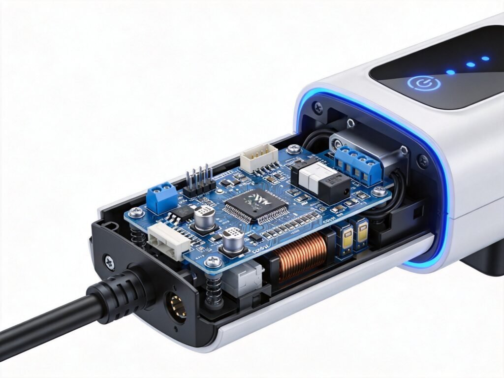
Key Takeaway for B2B Buyers
CP (Control Pilot) manages the charging handshake and current negotiation between vehicle and charger; PP (Proximity Pilot) confirms the cable connection and maximum current rating. Poor CP/PP design is the #1 cause of charging failures in portable EV chargers.
Control Pilot vs Proximity Pilot: The Signaling Circuits Every EV Charging Equipment Buyer Must Understand
If you source portable EV charging equipment for the European market, you have already checked power ratings, connector types, and certification marks. But there is a critical part of every EV charger that buyers rarely examine in detail — the control and signaling circuits defined in the IEC 61851 standard. These two invisible systems — the Control Pilot (CP) and the Proximity Pilot (PP) — govern every phase of the charging session, from the moment the plug is inserted to the instant energy stops flowing. Understanding how they work is not just an engineering exercise. It directly affects product safety, vehicle compatibility, and your ability to avoid costly returns from the field.
European Market Briefing
The EU now has over 1.1 million public EV charging points — five times the 2020 level — with 26 of 27 member states exceeding the AFIR fleet-based capacity targets by 180%. Meanwhile, the European EV charging equipment market is projected to reach $9.87 billion in 2026, growing at 12.7% year-on-year. With this expansion comes stricter regulatory enforcement: since January 2026, the updated EN IEC 61851-1:2023+A1:2025 standard mandates tighter tolerances on over-temperature protection response times and encrypted communication protocols. Every piece of portable charging equipment entering the EU must demonstrate full compliance with these signaling requirements.
What Is the Control Pilot (CP) Circuit?
The Control Pilot is the primary communication channel between the EV charging equipment and the electric vehicle. Defined in IEC 61851-1, it uses a Pulse Width Modulation (PWM) signal on a dedicated control wire running through the charging cable. The PWM duty cycle directly tells the vehicle how much current the EVSE can supply:
- 10% duty cycle = 6A
- 16.7% duty cycle = 10A
- 50% duty cycle = 32A
- 80% duty cycle = 51.2A (three-phase only)
The CP circuit also manages voltage-based state signaling that determines where the charging session stands at any given moment:
- State A (12V DC): EV not connected — charger is in standby
- State B (9V DC): EV connected but not yet charging — vehicle has acknowledged the connection
- State C (6V DC): EV is actively charging — vehicle has closed its internal contactor
- State D (3V DC): EV is charging and requests ventilation (rarely used in modern vehicles)
- State E (0V): Short circuit on the control pilot — fault condition
- State F (-12V): Error — charger has detected a fault and halted output
Every state transition must occur within milliseconds. If your equipment’s CP circuit produces an unstable PWM signal or slow voltage transitions, vehicles will reject the connection, throw error codes, or disconnect mid-session.
What Is the Proximity Pilot (PP) Circuit?
While the CP circuit handles charger-to-vehicle communication, the Proximity Pilot serves a different but equally vital purpose — it detects the cable’s current-carrying capacity and confirms that the plug is fully and securely inserted. For more details, explore our guide on EV charging connector standards. To learn more about this topic, see our article on single-phase vs three-phase EV charging equipment. For more details, explore our guide on single-phase vs three-phase EV charging equipment. To learn more about this topic, see our article on EV charging connector standards.
The PP circuit works through a simple but effective resistor-based mechanism. A resistor inside the vehicle connector (or charging plug) creates a voltage divider that the equipment reads to determine the maximum safe current for the attached cable:
- 680 Ω resistor: Signals a 6A cable capacity
- 220 Ω resistor: Signals a 16A cable capacity (typical for lightweight portable chargers)
- 100 Ω resistor: Signals a 32A cable capacity (standard for 7 kW portable units)
For OEM and ODM manufacturers, this has a direct implication: if you supply equipment with interchangeable or detachable cables, the PP resistor values must precisely match the cable’s rated capacity. An incorrect reading could allow the equipment to draw more current than the cable can safely handle — a serious safety hazard and a compliance violation under EN IEC 61851.
The PP circuit also serves as a mechanical lock detection mechanism. When the connector is not fully inserted, the PP resistance changes, and the equipment will not energize the power lines. This prevents partial-contact arcing, one of the most common causes of connector damage in field use.
Why This Matters for B2B Buyers: 5 Procurement Checkpoints
Understanding CP and PP is not academic — it has real commercial consequences. Here is what B2B buyers should verify with their suppliers before placing bulk orders:
1. PWM Accuracy and Stability
Request oscilloscope test reports showing the CP PWM signal accuracy. Tolerance should be within ±2% of the target duty cycle. Suppliers using low-quality PWM generators often produce jittery signals that cause intermittent charging failures in the field.
2. State Transition Timing
IEC 61851 requires state transitions within defined time windows. Ask your supplier for test evidence that State A→B→C transitions complete within the standard’s timing requirements (typically under 200 ms for initial handshake). Slow transitions can cause vehicle-side error codes and customer complaints.
3. PP Resistor Precision
Verify that PP resistor values are within ±1% tolerance. Cheap resistor components drift over time and under temperature stress, causing false cable detection readings. This is particularly important for portable chargers that operate across a wide temperature range (-25°C to +50°C in the European market).
4. Digital Communication Readiness
The updated EN IEC 61851-1:2023+A1:2025 standard adds requirements for encrypted communication to support ISO 15118 Plug & Charge. Buyers sourcing equipment for the 2026–2027 market should verify whether the supplier’s CP circuit supports both legacy analog PWM and the emerging digital Power Line Communication (PLC) overlay — or at least has a clear upgrade path.
5. Interoperability Testing
Request test reports showing compatibility with at least 10 popular European EV models. The CP protocol has minor implementation variations across vehicle manufacturers (Volkswagen Group, BMW, Renault, Stellantis, Hyundai-Kia), and equipment should be validated against each platform.
How ChuangRui Addresses CP and PP Compliance
At ChuangRui, every portable charging gun and EV charging unit we manufacture features precision CP and PP circuits designed and tested to full IEC 61851-1 compliance. Our engineering team validates PWM signal accuracy, state transition timing, and PP resistor precision across our entire product range — from 16A portable units to 32A adjustable models.
All ChuangRui products carry CE, UKCA, UL, RoHS, and REACH certification, backed by IATF 16949 automotive-grade quality management. Our OEM/ODM services include customized CP protocol configuration, cable selection with matched PP resistors, and full interoperability testing against your target vehicle platforms. With 7–15 day standard delivery and in-house testing labs, we help B2B buyers bring compliant, reliable charging equipment to market faster.
Ready to evaluate a supplier that treats signaling circuit quality as seriously as power output? Contact our engineering team for a technical consultation.
Contact ChuangRui
Chat on WhatsApp
+86 13757774567
Quick questions? Our team replies within 2 hours.
https://wa.me/8613757774567
Request our certification package
CE / UKCA / UL / RoHS / REACH / IATF 16949 documentation available on request.
https://crevcc.com/contact-us-4/
Request a quote — 24h response
Tell us your specifications and target volume. We will respond within one business day.
https://crevcc.com/contact-us-4/
#EVCharging #ControlPilot #IEC61851 #PortableEVCharger #OEM #B2B #ChuangRui #EVCharger
📚 References
Frequently Asked Questions
❓ What is the Control Pilot (CP) signal?
The CP is a PWM (Pulse Width Modulation) signal between the charger and vehicle that communicates: (1) charger availability (state A→B→C), (2) maximum available current (via PWM duty cycle), and (3) charging status. It runs on a ±12V signaling circuit.
❓ What is the Proximity Pilot (PP) signal?
The PP confirms the physical cable connection and communicates the cable’s maximum current rating to the vehicle. It uses a resistor in the connector: 680Ω = 16A, 220Ω = 32A. The vehicle reads this resistance to limit current draw.
❓ Why is CP/PP design quality critical for portable chargers?
The CP/PP circuit is the brain of the charging handshake. Component tolerance drift, EMI interference, or firmware bugs in the CP circuit cause: charging failures, intermittent disconnections, vehicle error codes, and the #1 source of customer complaints in portable chargers.
❓ How can B2B buyers evaluate a supplier’s CP/PP design quality?
Request: (1) CP/PP waveform oscilloscope screenshots showing clean PWM signal, (2) compatibility test reports with multiple vehicle brands (VW, Tesla, BYD, Renault), (3) EMI immunity test results (IEC 61000-4 series), and (4) temperature cycling test data for the CP circuit board.
❓ What are the most common CP/PP failures in field use?
Three failure modes: (1) PWM duty cycle drift due to temperature (charger shows wrong max current), (2) PP resistor tolerance shift (vehicle limits to lower current or refuses to charge), (3) EMI-induced false state transitions (charger randomly stops during charging). All three are PCB design quality issues.

About the CREVCC Engineering Team
Our engineering team brings 12+ years of experience in EV charging system design, from PCB layout and power electronics to international certification compliance.


